Basic Properties of Magnets
In order to achieve an optimal design according to the use, we will provide a guide on the basic properties of the magnets required and the fundamental equations for designing the magnetic circuit for your consideration. Please make use of them as reference material for a more efficient design.
1.Magnetic Hysteresis Loop (BH Curve)
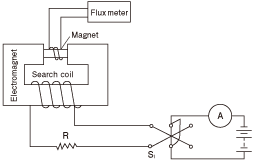
As shown in Figure 2, the magnetic flux density in the magnet increases as the current in the coil increases gradually to magnetize the magnet until it finally reaches saturation at a certain point. (Point a in the figure)
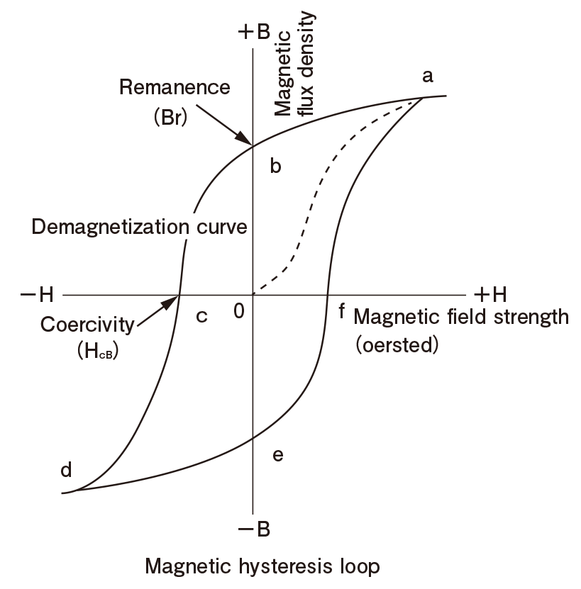
Subsequently, when the strength of the magnetic field is reduced by lowering the current from this saturated state, the magnetic flux density decreases from point a to point b without returning to 0. The magnetic flux density remains at point b even if the strength of the magnetic field becomes 0. This value is known as the remanence Br.Next, if the direction of the current is reversed and the magnetic field is increased in the opposite direction, the magnetic flux density decreases gradually from point b until it finally reaches 0 at point c. The strength of the magnetic field at this point is known as the coercivity or coercive force HcB.
If this reverse magnetic field is increased further, the magnet will be magnetized in the opposite direction until it reaches saturation at point d. In this way, by gradually changing the magnetic field, the magnetic flux density of the magnet changes according to a fixed cycle from a to b to c to d to e to f. This cycle is known as the magnetic hysteresis loop or BH curve.
2.Impact of Demagnetization Field (Self-demagnetization Effect)
As shown in Figure 3, although the magnetic field generated on the surface of a magnetized magnet faces the S pole from the N pole, a magnetic field Hd acts in the opposite direction to the magnetization direction I inside the magnet. This internal magnetic field is known as a demagnetization field and since it acts in a direction to demagnetize the magnet, it is always represented in the second quadrant of the magnetic hysteresis loop in Figure 1 when a magnet is used. The curve in this section is known as the demagnetization curve.
This demagnetization field varies according to the proportions of the magnet, becoming smaller the longer and narrower the magnet is in the magnetization direction. In practice, the impact of this demagnetization field is often represented by the slope Bd/Hd, which is the ratio of the demagnetization field to the magnetic flux density. This ratio is known as the permeance coefficient P=Bd/Hd. The straight line traced by the permeance coefficient is known as the operating line and the intersection point of this line with the demagnetization curve is known as the operating point.

The product of Hd and Bd corresponding to the operating point is known as the magnetic energy and this value is the highest at a certain operating point. The value at this point is known as the maximum energy product BHmax and this BHmax serves as an important material property value of a magnet.
3.External Impact
The operating point of a magnet will move and the magnetic force will change when a magnetic field is applied from the outside or when a piece of soft iron is brought near the magnetized magnet.
a.When a piece of soft iron is brought near a magnet
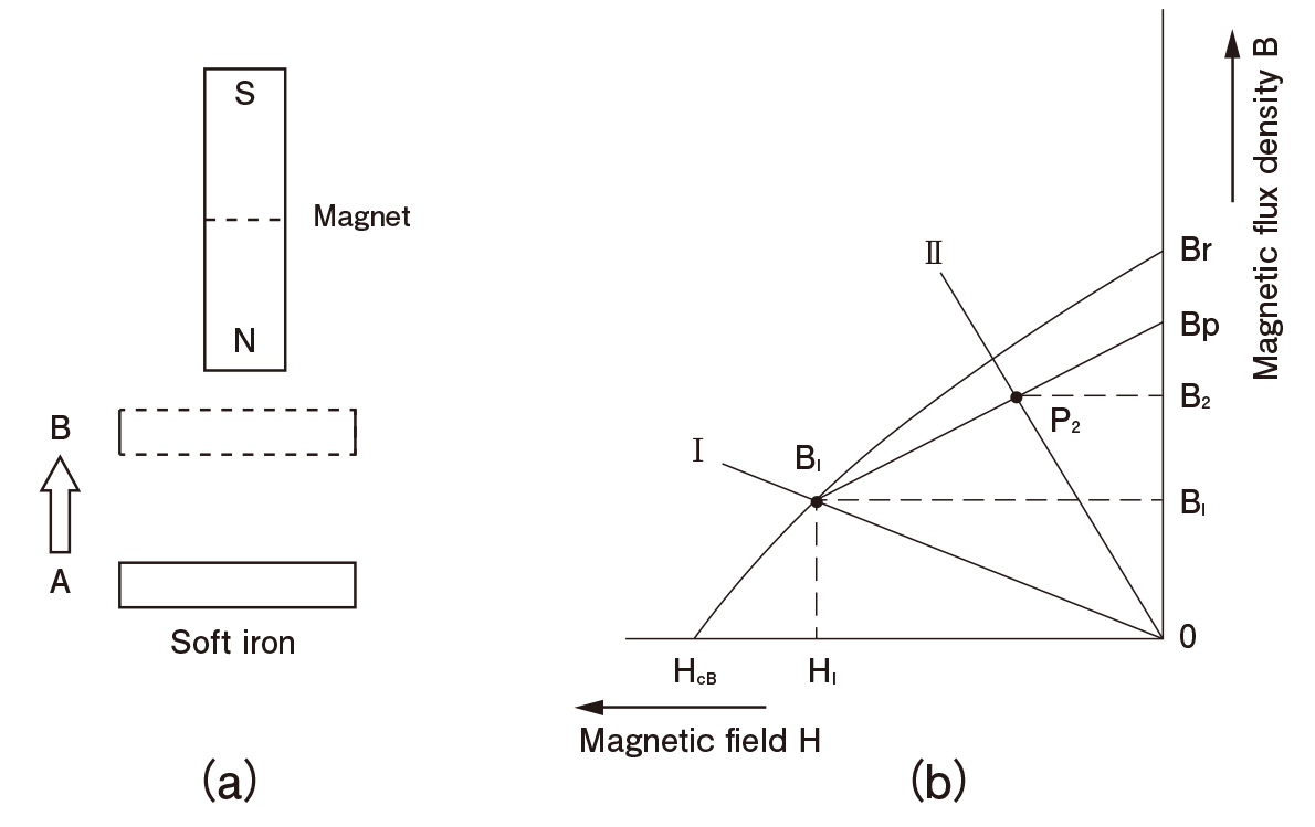
As shown in Figure 4 (a), the magnetic force of a rod magnet changes when a piece of soft iron is brought near the magnet. This is because the soft iron magnetized by the magnet creates a magnetic field on the outside which acts in a direction to strengthen the magnetic force of the magnet. When analyzing this action with the demagnetization curve, the permeance coefficient of the magnet changes depending on the position of the soft iron. Assuming that the permeance coefficient at Position A is I, the permeance coefficient at Position B will become larger and change to II due to a reduction in the length of the vacant space. At this point, the operating point will follow a separate path from the demagnetization curve starting from point P1 to reach point P2as shown in Figure 4 (b).This path P1-Bp can be approximated by a straight line known as a recoil line. The gradient of this straight line μr=(Bp-B1)/H1 is known as the recoil magnetic permeability. μr is a material constant and this gradient is roughly the slope of the tangent to the demagnetization curve at the point Br. In a ferrite magnet, μr usually shows a value of between 1.05 and 1.2.
When the operating point moves from point P1 to P2 the magnetic flux density increases from B1 to B2. Care is required in measuring and evaluating magnetic forces as the magnetic force changes when a piece of soft iron is located near the magnet as shown here.
b.When a reverse magnetic field is applied on a magnet
When an external magnetic field is applied in the opposite direction on a magnetized magnet, the magnetic flux density may change and the magnet may be demagnetized. This action can also be analyzed using the demagnetization curve. Although the BH curve expresses the change in the magnetic flux density when a magnetic field is applied on a magnet, the value of B at this point also includes the strength of the external magnetic field applied on the magnet in addition to the magnetic strength of the magnet itself.
B=μ0H+I μ0:Magnetic permeability of a vacuum
In the Cgs unit system, the magnetic strength of a magnet is expressed as 4πI and B=4πI+H.
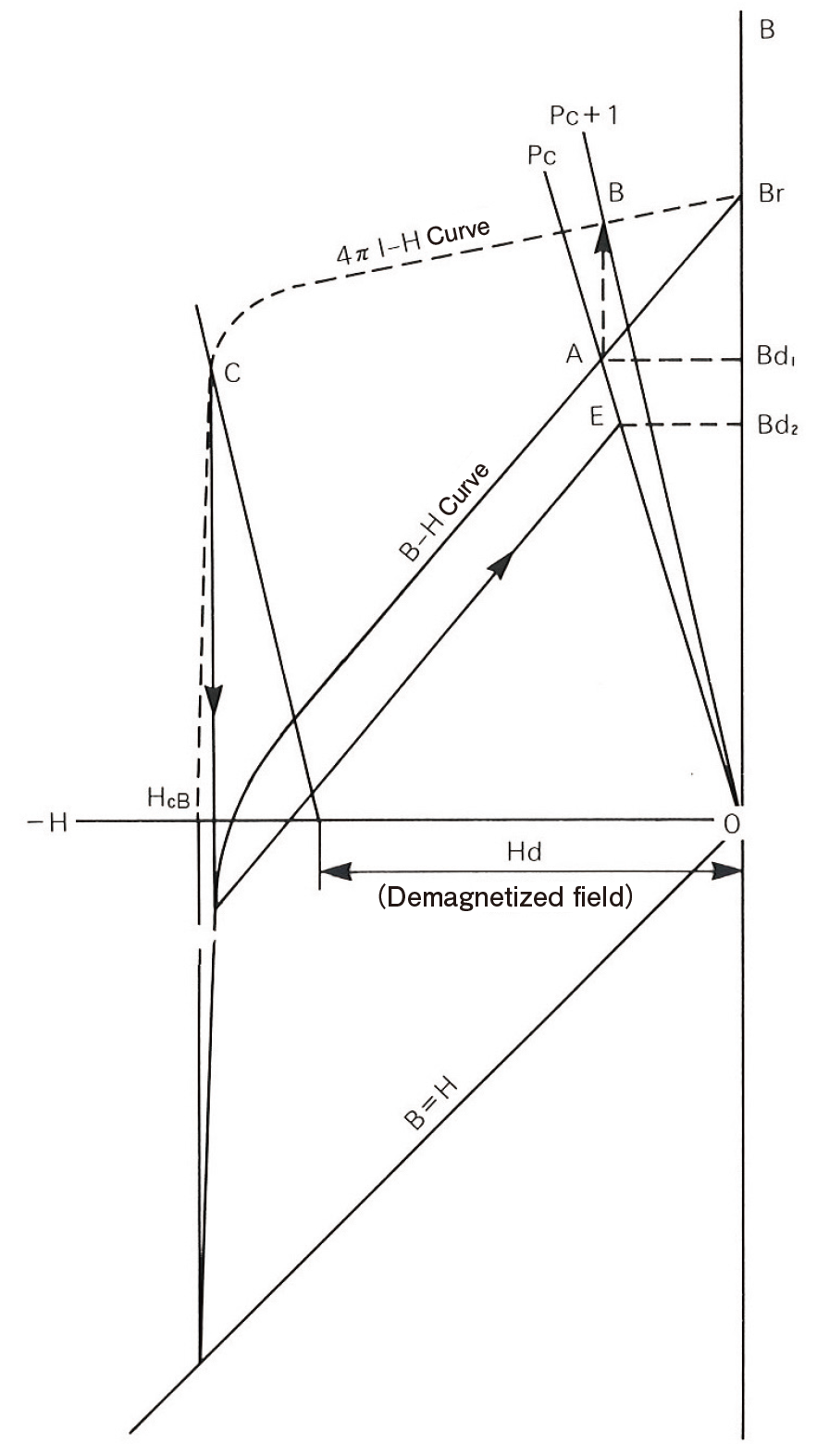
A curve that cancels out the impact of this external magnetic field in expressing the relationship between the magnetic strength of the magnet itself and the external magnetic field is known as the 4πI-H curve. Figure 5 shows the BH curve and 4πI-H curve. The coercive force HcB on the BH curve is the strength of the magnetic field in which the magnetic flux density of the magnet apparently becomes 0, while the strength of the magnetic field in which the magnetization strength 4πI of the magnet itself becomes 0 is known as HcJ. Therefore, after an external magnetic field with exactly the same magnitude as HcJ is applied, upon removing the external magnetic field, the remanence of the magnet becomes zero completely. In this sense, HcJ is said to be the true coercivity. When a demagnetization field acts on a magnet due to an external magnetization field, there is a need to analyze this with the 4πI-H curve rather than the BH curve depicted in the second quadrant.
In Figure 5, assuming the intersection point of the 4πI-H curve with the perpendicular that is raised from the operating point A with a permeance coefficient Pc is point B, then point B indicates the magnetization force when subjected to the impact of the self-demagnetization field alone without the influence of the external magnetic field. Considering the case of a demagnetization field Hd acting here, since the magnetization force when the demagnetizing field Hd is acting is expressed by the intersection point C between the 4πI-H curve and an operating line drawn parallel to the straight line 0B, if you drop a perpendicular from this point C and take the intersection point of this line with the BH curve as point D, then point D represents the operating point when the demagnetization field Hd is acting on the magnet. If this demagnetization field Hd is removed, the operating point will move along the recoil line to the intersection point E with the permeance coefficient Pc. Therefore, ultimately the magnet is demagnetized irreversibly by the amount Bd1-Bd2 alone.
When using a magnet at a low temperature, this demagnetization ratio becomes even larger due to temperature changes of the BH curve. In this case, it is recommended that the magnet be designed with a permeance coefficient that is as high as possible while choosing a material with a high HcJ at the same time.
4.Low Temperature Demagnetization of a Ferrite Magnet
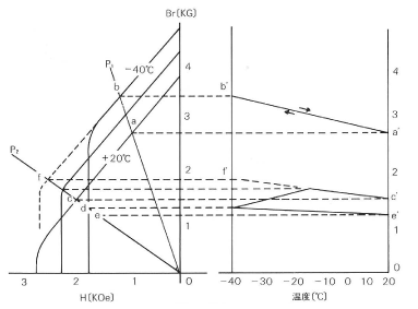
If the permeance coefficient of an anisotropic ferrite magnet is not high, when it is cooled at a low temperature close to −40°C and then returned to normal temperature again, the magnet will exhibit a large demagnetization effect. Generally, the change in the magnetic force of a ferrite magnet due to a change in temperature is expressed by the respective temperature coefficients Br and Hc as shown in Table 2, with △Br/Br/°C≒−0.18 – −0.19%/°C and △H/H/°C≒+0.35 – 0.5%/°C. The operating point will move since the BH curve will fluctuate together with these rates of change. For a magnet with a permeance coefficient of P1 as shown in Figure 6, the operating point at point a at a temperature of 20°C will move to point b at a temperature of −40°C. The gradient from point a' to point b' depends on the temperature coefficient of −0.18 – −0.19%/°C. The operating point returns to point a again if the temperature is returned to 20°C. However, for a magnet with a permeance coefficient of P2, although the BR operating point at point c at a temperature of 20°C will move from point c to point f at a rate of −0.18 – −0.19%/°C as the temperature gets lower, Hc will be inverted midway and come to point d at a temperature of −40°C as it will decrease at a rate of +0.35 – +0.5%/°C. If the temperature is moved back to 20°C, this time Hc will come to point e from point d at the same rate again. Thereafter, at a temperature between −40°C and +20°C, it will move back and forth between points d and e.
